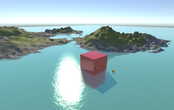
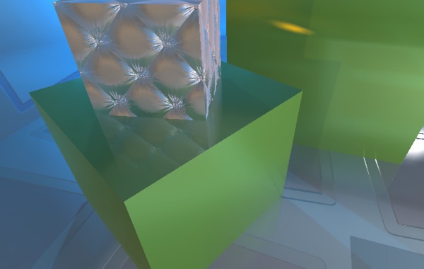
While working on my GGJ15 prototype I had the opportunity to play some more with Unity 5's new physically based rendering. The look I had in mind for the prototype was semi-futuristic, clinically clean spaces with as close to a pre-rendered appearance as possible. While Unity 5 makes this kind of thing very easy to setup, especially with it's new ReflectionProbes, there was one glaring omission. Real-time reflections of non-static objects.
I've read various papers and articles on screen space reflections over the past year and this seemed like a perfect opportunity to attempt my own implementation. It's been a great learning experience on a variety of topics, not least Unity's entire rendering pipeline, so I wanted to write a full article documenting the process in the hope that it will help others wrap their heads around screen space reflections and some of the lesser documented parts of Unity rendering.
For the TLDR types, I'm making my full implementation open source under the BSD license. You're free to use it as you wish, including in commercial projects, although I kindly ask that you don't just repackage it and throw it on the Unity Asset Store. You can view the repo here on GitHub, I will happily consider all pull requests.
Local Reflections, a Naive Approach
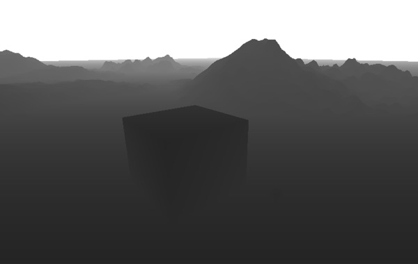
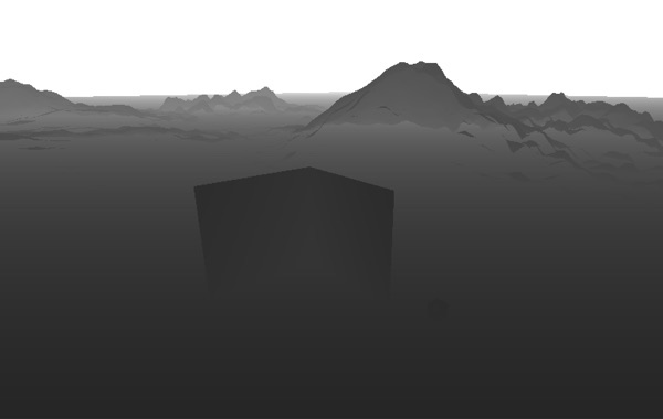
In classic ray tracing an image is rendered by tracing rays of light to their intersection point with scene geometry. By finding the surface closest to the camera for each pixel in the destination image and calculating which lights are hitting that surface and how, a final color value can be constructed for that pixel. Typically raytracers use a full rendering pipeline to do this with access to all information about the scene's geometry, materials and lighting. It turns out however that we can use the same approach in image space with depth, normal and material pre-passes, much like the various GBuffers used in deferred rendering.

In Unity we have access to all this information readily available. By setting the Camera component's depthTextureMode property to DepthTextureMode.DepthNormals, any post processing shader placed on that camera is automatically passed a Sampler2D named _CameraDepthNormalsTexture that contains both linear depth and camera space normals for each pixel rendered. With just this information alone we can construct the camera space position of the closest surface for each pixel in a fragment shader and then calculate the reflection vector from the camera to that surface's normal. With the camera space position of the surface and the reflection vector we have everything we need to trace a ray of light as it bounces off that surface.
Post processing effects in Unity are handled by rendering a full screen quad, usually displaying the frame buffer, using a specific shader. By taking the UVs of this quad in the vertex shader, converting them to NDCs and transforming them using the inverse projection matrix we can trivially calculate the four corners of the far clip plane in camera space. Passing these to the fragment shader results in them being interpolated across the screen and thus gives us the appropriate ray from the camera to the far clip plane for every pixel. Multiplying this ray by the linear depth sampled in the fragment shader gives us the camera space position of the current pixel.
// Calculate camera to far plane ray in vertex shader
float4 cameraRay = float4( vertex.uv * 2.0 - 1.0, 1.0, 1.0);
cameraRay = mul( _CameraInverseProjectionMatrix, cameraRay);
output.cameraRay = cameraRay.xyz / cameraRay.w;
// Calculate camera space pixel position in fragment shader
float3 decodedNormal;
float decodedDepth;
DecodeDepthNormal( tex2D( _CameraDepthNormalsTexture, input.uv), decodedDepth, decodedNormal);
float3 pixelPosition = input.cameraRay * decodedDepth;
By normalizing the current camera ray we can now calculate the reflection vector with the sampled surface normal for that pixel. With the camera space position and the reflection vector we now know where our ray starts and the direction it should move in. To calculate the ray's end point we simply multiply the normalized reflection vector by our maximum ray distance setting and add this to the ray's starting point. With the ray's starting point and ending point known we can now divide the delta of the two points by our iteration setting giving us a step vector. Now all we have to do is loop for the number of iterations we've decided on, adding the step vector each iteration and sampling the depth buffer at the current point. If the ray is behind the current depth value (but still within some predetermined range) we can consider this an intersection and sample the frame buffer at this point, giving us our reflected pixel. If the ray never intersects the scene then we simply return the original fragment from the frame buffer.
Casting a Ray in Screen Space
While the above approach is easy to understand and implement it has one major issue. Since we are casting the rays linearly in camera space there is a high chance that some rays will skip large parts of the scene while others will spend the entire time moving through what equates to just one or two pixels in screen space. Consider a ray bouncing off the left wall of a room towards the room's back wall. While this ray may be the full distance we've designated, when transformed into screen space it may only move a few pixels, yet we will still sample this ray at every step of the way.
To fix this issue we need a way of casting the ray such that each step will always move at least one pixel horizontally or vertically in screen space, thus guaranteeing that we are never sampling more or less than needed. To attack this we must consider our ray as a 2D line in screen space. Using perspective correct interpolation of the ray's starting point and end point Z value we can trace the ray in screen space while still having access to the camera space depth at each step of the way.
When camera space vertices are transformed by the projection matrix the resulting homegonous coordinates must be divided by their W component to calculate the final projected screen space position. On the GPU this is handled automatically and is how the fragment shader receives it's perspective correct interpolated values such as vertex colors and UVs. For our screen space ray tracer we can employ the same approach. Using the projection matrix we can transform the camera space ray start and end points to homogenous coordinates and linearly interpolate their Z and W components. Then for each iteration of our ray casting loop we simply divide the current homogenous Z by W to retrieve the camera space depth at that point.
For all intents and purposes this is a 2D line rendering problem and so we can use the standard DDA approach to calculate our screen space ray. This post by Morgan McGuire was instrumental in my understanding of this problem and provides an interesting GPU friendly DDA implementation that my final CG ray casting code was largely based on.
Camera vs. GBuffer Normals
Once I had my initial SSR implementation up and running, one thing immediately stood out. Reflections looked fine with a stationary camera but as soon as the camera rotated, the reflections would wobble slightly. Slowly rotating the camera a few degrees back and forth really illustrated the issue as reflection angles would be correct and then slightly wrong and then snap to correct.
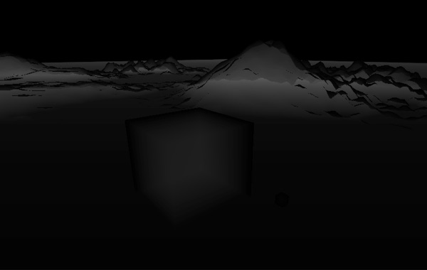
While Unity's Camera DepthTextureMode.DepthNormals is convenient, encoding a normal and depth value into 32 bits is not free, the cost is precision and the result in this case was reflection wobble. Luckily the RGB components of _CameraGBufferTexture2 contain the current pixel's world space normal and with a little extra math in the fragment shader we can convert this to a camera space normal. Switching to world space normals completely fixed the reflection wobble and reminded me to always be aware of precision issues and their side effects.
// In C# script
material.SetMatrix( "_NormalMatrix", camera.worldToCameraMatrix);
// In fragment shader
float3 worldSpaceNormal = tex2D( _CameraGBufferTexture2, i.uv).rgb * 2.0 - 1.0;
float3 cameraSpaceNormal = mul( (float3x3)_NormalMatrix, worldSpaceNormal);
Switching to world space normals not only fixed the reflection wobble issue but also came with another benefit. Since we no longer use DepthTextureMode.DepthNormals we can switch to DepthTextureMode.Depth which uses the full 32 bits to store depth. The extra precision provided by DepthTextureMode.Depth not only helps in the general ray cast but also in calculating geometry thickness, covered in the next section.
Calculating Geometry Thickness
At each step of the ray cast we must check for an intersection between the ray and the scene geometry. All implementations I've read about do this by either considering any depth buffer value greater than the ray's current depth an intersection or by defining a constant pixel thickness and checking if the ray's current depth is inside the pixel (i.e. less than the depth buffer value but greater than the depth buffer value minus pixel thickness). The former results in many false positives, rays cannot travel behind objects. The latter results in false negatives, particularly when a scene contains a wide range of depths (imagine a huge mountain with a human standing at the bottom).
In an effort to solve this problem I was reminded of a technique used to fake sub-surface scattering. By rendering a second depth buffer with frontface culling enabled we can calculate per-pixel thickness of rendered geometry by simply subtracting frontface depth from backface depth. With this value available to us we no longer need to tweak a pixel thickness constant based on scene, can have rays that pass behind objects and drastically increase the variety of scenes where SSR is a viable option.
Since we are only using the backface depth buffer to calculate per-pixel thickness and already have a full resolution frontface depth buffer, it is entirely possible to reduce it's resolution at little to no impact on visual quality. Artifacts that may arise from a lower resolution backface depth buffer are reflection discontinuities around object edges but these tend to only become noticeable at extremely low resolutions and are largely scene dependent. In certain test scenes I was able to use a backface depth buffer 6x smaller than screen resolution while still maintaining acceptable fidelity.
Binary Search Refinement
When casting a ray linearly we can lower the number of iterations required by increasing the step size. Working in screen space we can do something similar by introducing a pixel stride setting that dictates the number of screen pixels between ray steps. In both cases we are sacrificing visual accuracy for performance. Using binary search we can regain some of that accuracy at a very small cost by simply refining the final step of the ray trace.
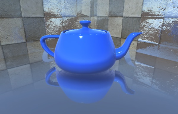
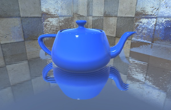
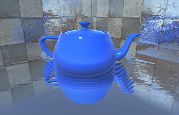
If we are using a pixel stride greater than 1 and we detect an intersection between the ray and the scene we can take one step back, divide the step size by two and step forward. At this point we are halfway between the final two steps. If the ray is still intersecting the scene then we halve the step size again and step back, if not we halve the step size and move forward, essentially conducting a binary search for ray intersection between the final two coarse steps.
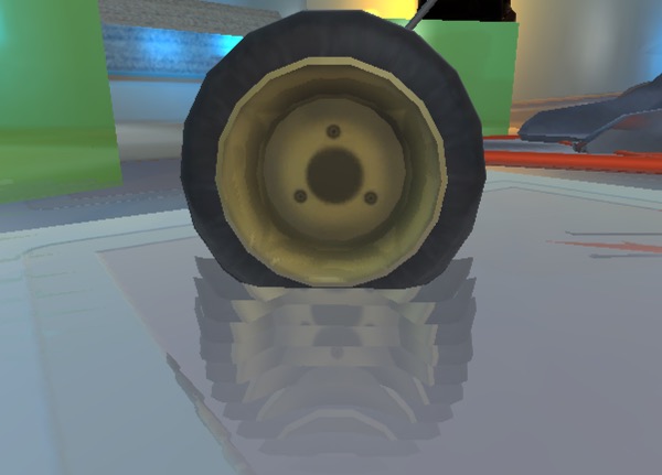
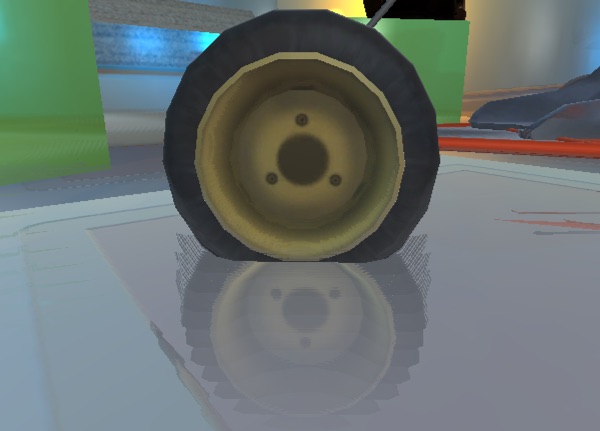
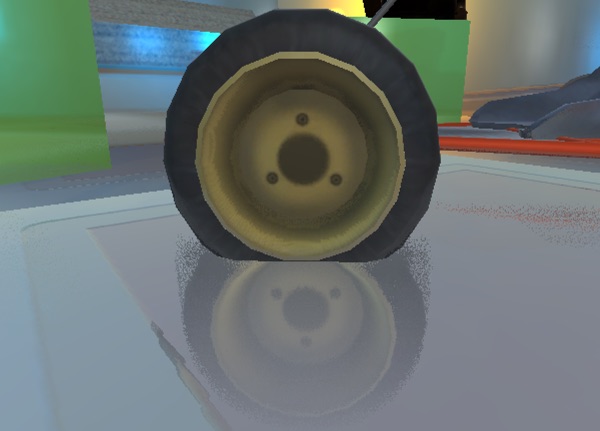
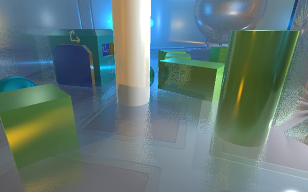
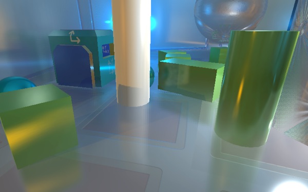
Binary search refinement is not a silver bullet. When using a large pixel stride setting there is still a high chance of missing intersections, particularly with thin pieces of geometry. However, when an intersection is detected binary search refinement greatly increases the accuracy for very few additional iterations. In the example screenshots of the go-cart wheel you can see that with low precision settings (maximum iterations 10, pixel stride 40) and binary search disabled the reflection is incorrect, yet with only 4 additional iterations of binary search the reflection is largely correct and finally by raising the jitter setting we end up with a close to perfect reflection.
Hiding Artifacts
As SSR is a screen space post processing effect, the number one cause of artifacts is lack of scene information. To hide these artifacts we must detect rays that will intersect parts of the scene for which we have no information and smoothly fade out these reflections. There are three primary cases we must account for; rays that leave the camera frustum, rays that are moving towards the camera and rays that go beyond the maximum iteration/distance settings. Luckily these are all fairly trivial to handle.
When a ray intersects scene geometry in the depth buffer we return a UV coordinate to sample the pixel at that point in the frame buffer. By converting this UV coordinate to NDC space we can simply check the absolute value in either dimension to see how close it is to the screen edge. When a ray reaches 1.0 in either dimension it is at the screen edge and thus should be completely transparent. By defining a range between 0.0 and 1.0 we can control when reflections will start to fade based on their distance from the screen edges.
We can assume that any ray traveling towards the camera will hit back facing geometry and thus should also be smoothly faded. Since we are working in camera space any ray that's direction has a positive Z value is moving towards the camera, thus we can define another 0.0 to 1.0 range for smoothly fading based on the ray direction's Z value.
Finally, to fade out reflections that reach either the maximum iteration or distance limits we must divide by the relevant value. When a ray collides with scene geometry we take the number of steps it took to get there and divide by our maximum iteration setting. After this we calculate the camera space distance from the ray origin to the collision point and divide this by our maximum distance setting.

As you may have noticed, all the above calculations result in a value from 0.0 to 1.0. By multiplying all of these values together we end up with a single value between 0.0 and 1.0, this is our final alpha value used to blend the reflection sample with the original frame buffer sample.
Faking Glossy Reflections
In the world of physically based rendering all materials have a roughness or gloss value that defines the microstructure of a surface. In layman's terms, how blurry or sharp reflections appear. With Unity 5's new physically based materials we can access this value on a per-pixel basis straight from the GBuffer by adding a Sampler2D named _CameraGBufferTexture1 to our shader and reading the alpha component.
The first approach I tried when emulating roughness was to use the GBuffer value as a scaler for a random vector which was then added to the surface reflection vector before casting the ray. In essence this is what's happening at the micro level of rough surfaces and to a degree it works. As roughness and ray distance increase however, the quality deteriorates manifesting as stippling in the final reflection. While this can be mitigated somewhat with a blur pass it is difficult to completely eliminate shimmering on very rough surfaces.
With the more physically correct approach to surface roughness being a bust the next option was to fake it. Adding a custom image blur after the ray trace pass that alters it's kernel radius based on the roughness value from the GBuffer allows for fairly good looking, fairly cheap glossy reflections.
Adding a blur pass requires that we no longer blend the reflection sample directly but rather store the calculated alpha in the output pixel. Sending the raw reflection sample and calculated alpha through to the blur enables blurring of the alpha value, nicely softening the edges of reflected geometry. Once the two separable passes of the blur are complete a final simple shader blends the blurred sample with the original frame buffer sample using the (now blurred) alpha value we calculated in the ray trace pass.
Performance vs. Quality
Reading about screen space reflections you will often see mention of scene complexity having no impact on performance and to a certain degree this is true. Compared to an alternative such as planar reflections using duplicated mirrored geometry, that may itself require many separate complex materials, screen space reflections definitely offer a much more predictable performance hit and one that is likely to be more valuable as your scene's complexity increases. However, things such as clipping rays that leave the frustum and short rays due to spatially close geometry all have an impact on how quickly the ray trace pass will complete.
While screen space reflections are by no means a cheap effect they can easily offer better performance and quality than alternative approaches. Like most things in real-time graphics the best results come from carefully balancing performance vs. quality tradeoffs of all elements in a scene. The various settings in the ray casting pass as well as optionally downsampling the various passes all provide a high level of optimization on a scene by scene basis.
Lowering the number of ray cast steps while increasing the pixel stride is a key area for increasing performance, especially when doing a full resolution ray cast pass. In many scenes a surprisingly low number of iterations/large pixel stride can be used while still maintaining acceptable visual quality. In my implementation I attenuate pixel stride based on distance from camera which greatly minimizes artifacts caused by large strides for distant reflections.
One interesting optimization that I've read about but have yet to experiment with is using a hierarchical depth buffer. Using a custom depth rendering pass that stores the largest depth value of the next level up in the mip map chain we can use the depth buffer like a quad tree to minimize the number of steps taken for each pixel in the ray casting pass.
kode80 SSR is Open Source!
If you've made it this far, you've read through my longest article to date, I hope it was useful! As mentioned at the top, I'm making my full implementation open source under the BSD license. You're free to use it as you wish, including in commercial projects, although I kindly ask that you don't just repackage it and throw it on the Unity Asset Store. You can view the repo here on GitHub, I will happily consider all pull requests.